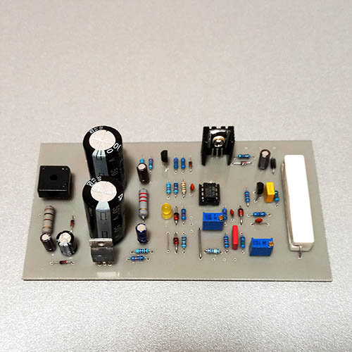
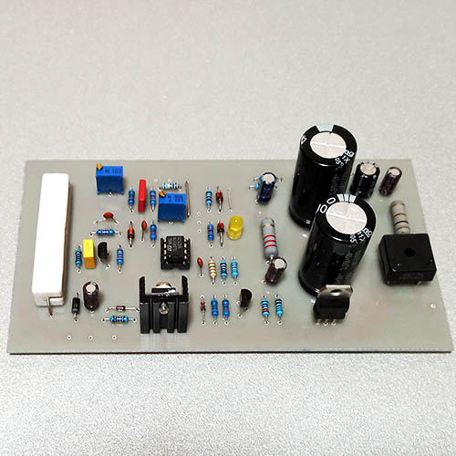
Laboratory power supply 0-30V/0-3A
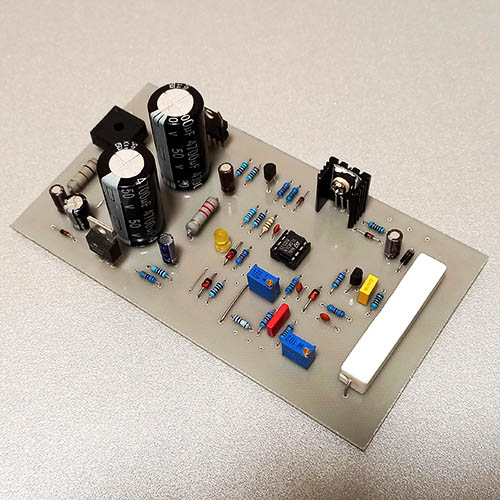
http://electronics-diy.com/adjustable-lab-power-supply.php
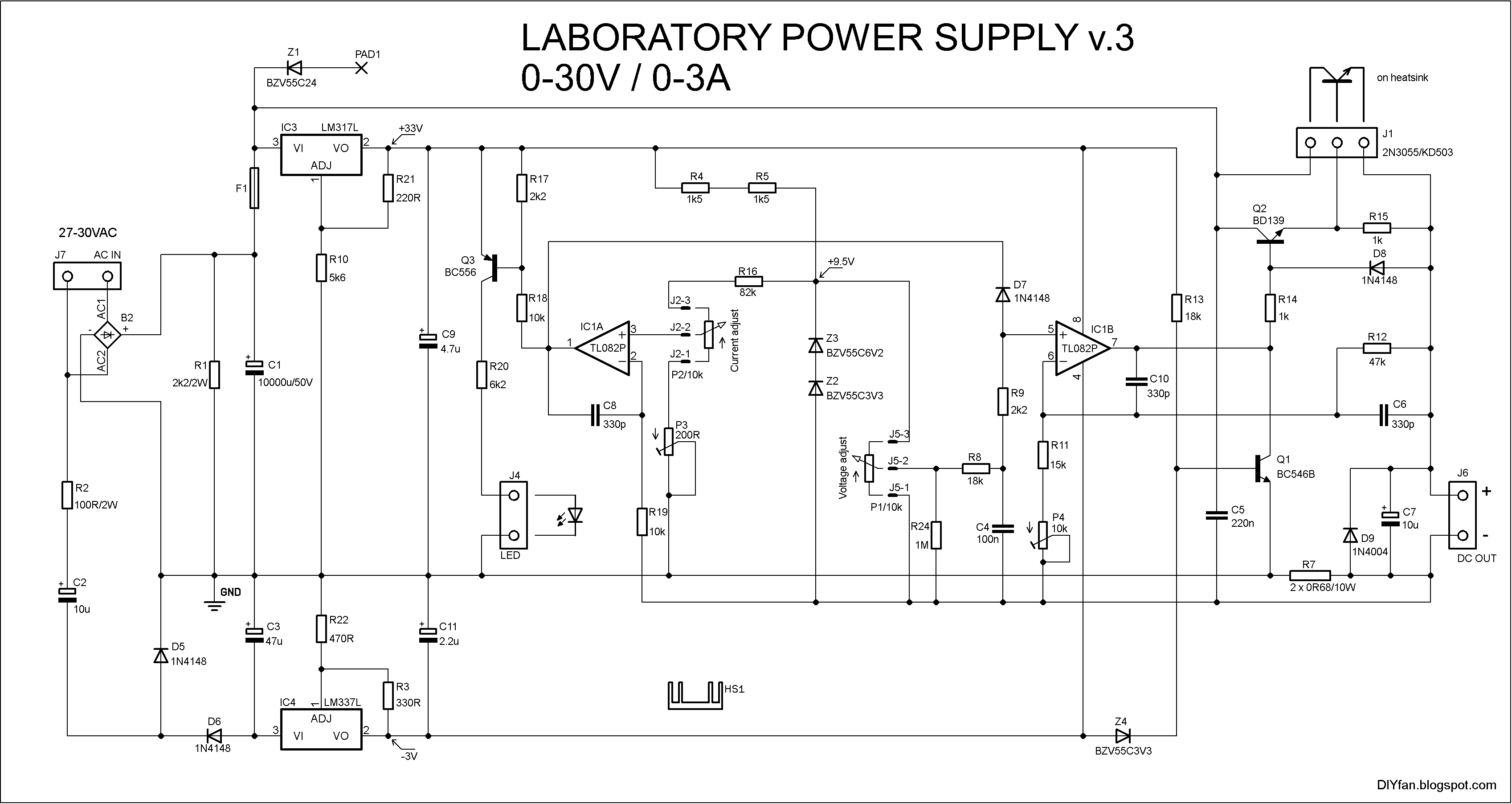
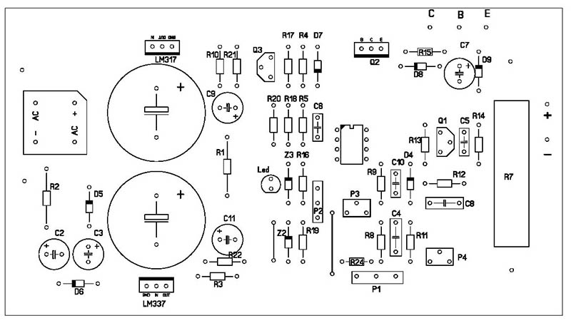
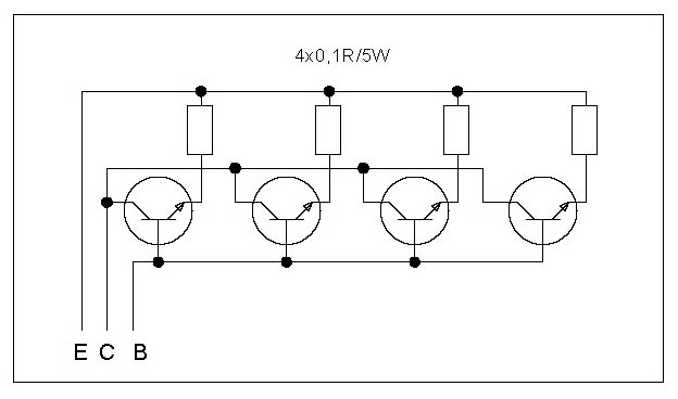
Presented here is a Laboratory Power Supply with 0-30V voltage and 0-3A current regulation. The schematic is pretty straightforward, it uses standard dual opamps such as TL082, TL062, TL072, NE5532, RC4558 and MC34072. The trimmer P3 adjusts the minimum current limit. P4 adjusts the maximum output voltage. After the final adjustment you may replace the trimmers with standard resistors. Power transistor dissipates quite a bit of heat and thus require a heatsink with optional fan. We may use two or tree transistors in parallel with emitter resistors to achieve more power. The transformer must be 100-120W with 27-30VAC output voltage.
For the current sensing resistor R7 I use two parallel resistors 0.68Ohm/10W. You may use a single 0.33Ohm/10W resistor but it will get too hot.
With R16 = 82k and R7 = 0.33Ohm the maximum current limit adjusted with P2 will be more than 3A – more like 3.3A. If we want to be closer to 3A then the R16 must be 91k.
The bizarre looking zener Z1 connected with PAD1 is used to power supply the digital voltmeter which indicates the output voltage. It requires 6-28V supply voltage and with that zener I reduce the input voltage to an acceptable level. Z1 may be omitted if not needed.
| Shema | OK |
| PCB | OK |
| Test | OK |
Files:
- PDF (Shema, PCB, Components placement)
- Tiny CAD (Shema)
- Sprint Layout (PCB, Components placement)
order exclusively by e-mail: info@myhobbyelectronic.me
